Stereo Panner
The default stereo panner distributes two inputs to two outputs. Its behaviour is controlled by two parameters, width and position. By default, the panner is centered at full width.
The stereo panner assumes that the signals to distribute are either uncorrelated (i.e. totally independent), or that they contain a stereo image which is mono-compatible, such as a co-incident microphone recording, or a sound stage that has been created with pan pots.*
With the default values it is not possible to alter the position, since the width is already spread entirely across both outputs. To alter the position, the width must first be reduced.
Stereo Panner User Interface

The panner user interface consists of three elements, divided between the top and bottom half. Clicking and/or dragging in the top half controls position; clicking and/or dragging in the bottom half controls width (see below for details).
In the top half is the position indicator, which shows where the center of the stereo image is relative to the left and right edges. When this is the middle of the panner, the stereo image is centered between the left and right outputs. When it all the way to the left, the stereo image collapses to just the left speaker.
In the bottom half are two signal indicators, one marked L and the other R. The distance between these two shows the width of the stereo image. If the width is reduced to zero, there will only be a single signal indicator marked M (for mono), whose color will change to indicate this special state.
It is possible to invert the outputs (see below) so that whatever would have gone to the right channel goes to the left and vice versa. When this happens, the entire movable part of the panner changes color to indicate clearly that this is the case.
Position vs. L/R
Although the implementation of the panner uses the "position" parameter, when the user interface displays it numerically, it shows a pair of numbers that will be familiar to most audio engineers.
| Position | L/R | English |
|---|---|---|
| 0 | L=50% R=50% | signal image is midway between left and right speakers |
| -1 | L=100% R=0% | signal image is entirely at the left speaker |
| 1 | L=0% R=100% | signal image is entirely at the right speaker |
One way to remember this sort of convention is that the middle of the USA is not Kansas, but "Los Angeles: 50% New York: 50%".
Examples In Use
| Appearance | Settings |
|---|---|
| Width=100%, L=50 R=50 |
 | Width=0%, L=50 R=50 |
 | Width=-100%, Position = 0 (center) |
 | Width=36%, L=44 R=56 |
 | Width=0%, L=0 R=100 |
Using the mouse
Mouse operations in the upper half of the panner adjust the position parameter, constrained by the current width setting.
Mouse operations in the lower half of the panner adjust the width parameter, constrained by the current position setting.
The position can be changed smoothly, by pressing the right button and dragging within the top half of the panner, then releasing. The position will be limited by the current width setting. Note: it is not necessary to grab the position indicator in order to drag.
The width can also be changed smoothly, by pressing the right button and dragging within the lower half of the panner, then releasing. The width will be limited by the current position setting. Note: it is not necessary to grab the L/R indicators in order to drag.
| Reset to defaults | Click right |
|---|---|
| Change to hard left | Double click right in the upper left half of the panner |
| Change to a hard right | Double click right in the upper right half of the panner |
| Move position as far left as possible, given width | Double click right in the upper left half of the panner |
| Move position as far right as possible, given width | Double click right in the upper right half of the panner |
| Set the position to center | Click right in the upper middle of the panner |
| Reset to maximum possible width | Double click right on the lower left side |
| Invert (flip channel assignments) | Double click right on the lower right side |
| Set width to 0° | Double click right in the lower middle |
Keyboard bindings
When the pointer is within a stereo panner user interface, the following keybindings are available to operate on that panner:
| ↑ / ↑ | increase width by 1° / 5° |
|---|---|
| ↓ / ↓ | decrease width by 1° / 5° |
| ← / ← | move position 1° / 5° to the left |
| → / → | move position 1° / 5° to the right |
| 0 | reset position to center |
| ↑ | reset width to full (100%) |
Using the scroll wheel/touch scroll
When the pointer is within a stereo panner user interface, the scroll wheel may be used as follows:
| ⇐ / ⇐ | increase width by 1° / 5° |
|---|---|
| ⇒ / ⇒ | decrease width by 1° / 5° |
| ⇑ / ⇑ | move position 1° / 5° to the left |
| ⇓ / ⇓ | move position 1° / 5°to the right |
Stereo panning caveats
The stereo panner will introduce unwanted side effects on
material that includes a time difference between the channels, such
as A/B, ORTF or NOS microphone recordings, or delay-panned mixes.
When the width is reduced, two highly correlated signals with a delay are
effectively summed, which will cause comb filtering.
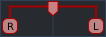
Let's take a closer look at what happens when a source is recorded at 45° to the right side with an ORTF stereo microphone array and then the width manipulated.
For testing, we apply a pink noise signal to both inputs of an Ardour stereo bus with the stereo panner, and feed the bus output to a two-channel analyser. Since pink noise contains equal energy per octave, the expected readout is a straight line, which would indicate that our signal chain does not color the sound:
An ORTF is simulated using Robin Gareus' stereo balance control LV2 to set the level difference and time delay. The Trim/Gain can be ignored—its purpose is just to align the test signal with the 0dB line of the analyser.
An ORTF microphone pair consists of two cardioids spaced 17 cm apart, with an opening angle of 110°. For a far source at 45° to the right, the time difference between the capsules is 350 μs or approximately 15 samples at 44.1 kHz. The level difference due to the directivity of the microphones is about 7.5 dB (indicated by the distance between the blue and red lines in the analyser).
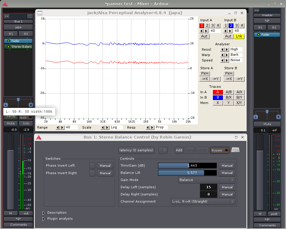
Now for the interesting part: if the width of the signal is reduced to 50%, the time-delayed signals will be combined in the panner. What happens to the frequency response of the left and right outputs is shown in the following picture:
It can be argued that all spaced microphone recordings will undergo comb filtering later, when the two channels recombine in the air between the speakers. Perceptually however, there is a huge difference: our hearing system is very good at eliminating comb filters in the real world, where their component signals are spatially separated. But once they are combined inside a signal chain, this spatial separation is lost and the brain will no longer be able to sort out the timbral mess.
Depending on the material and on how much the width needs to be manipulated, some degree of comb filtering may be acceptable. Then again, it may not. It is advised to listen carefully for artefacts when manipulating unknown stereo signals—many orchestra sample libraries for example do contain time-delay components.